Steel specifications and applications

General Requirements for Rolled Steel Plates, Shapes, Sheet Piling, and Bars
for Structural Use

 
Abstract:
This group of ASTM standard specifications covers a common requirements that, unless otherwise specified in the material specification, apply to rolled steel plates, shapes, sheet piling, and bars.
 
 
This group of ASTM standard specifications covers a common requirements that, unless otherwise specified in the material specification, apply to rolled steel plates, shapes, sheet piling, and bars under each of the following specifications issued by ASTM.
ASTM Designation Title of Specification
A 36/A 36M Structural Steel
A 131/A 131 M Structural Steel for Ships
A 242/A 242 M High-Strength Low-Alloy Structural Steel
A 283/A 283 M Low and Intermediate Tensile Strength Carbon Steel Plates, Shapes, and Bars
A 284/A 284 M Low and Intermediate Tensile Strength Carbon-Silicon Steel Plates for Machine Parts and General Construction
A 328/A 328 M Steel Sheet Piling
A 441/A 443 M High-Strength Low-Alloy Structural Manganese Vanadium Steel
A 514/A 514 M High-Yield Strength, Quenched and Tempered Alloy Steel Plate Suitable for Welding
A 529/A 529 M Structural Steel with 42 000 psi {290 MPa) Minimum Yield Point (12.7 mm Maximum Thickness)
A 572/A 572 M High-Strength Low-Alloy Columbium-Vanadium Steels of Structural Quality
A 573/A 573 M Structural Carbon Steel Plates of Improved Toughness
A 588/A 588 M High-Strength Low-Alloy Structural Steel with 50 ksi (345 MPa) Minimum Yield Point to 4 in. Thick
A 633/A 633 M Normalized High-Strength Low-Alloy Structural Steel
A 656/A 656 M Hot-Rolled Structural Steel, High-Strength Low-Alloy Plate with Improved Formability
A 678/A 678 M Quenched and Tempered Carbon Steel Plates for Structural Applications
A 690/A 690 M High-Strength Low-Alloy Steel H-Piles and Sheet Piling for Use in Marine Environments
A 699 Low-Carbon Manganese-Molybdenum-Columbium Alloy Steel Plates, Shapes, and Bars
A 709 Structural Steel for Bridges
A710/A710 M Low-Carbon Age-Hardening Nickel-Copper-Chromium-Molybdenum-Columbium and Nickel-Copper-Columbium Alloy Steels
A 769 Electric Resistance Welded Steel Shapes
A 786/A 786 M Rolled Steel Floor Plates
A 808/A 808 M High-Strength Low-Alloy Carbon, Manganese, Columbium, Vanadium Steel of Structural Quality with Improved Notch Toughness
A 827 Plates, Carbon Steel, for Forging and Similar Applications
A 829 Plates, Alloy Steel, Structural Quality
A 830 Plates, Carbon Steel, Structural Quality, Furnished to Chemical Composition Requirements

Descriptions of Terms Specific to This Standard

Plates (other than floor plates or coiled product) - Flat hot-rolled steel classified as follows:

When ordered to thickness:

  • Over 200 mm in width and over 6 mm or over in thickness.
  • Over 1200 mm in width and over 4.5 mm or over in thickness.
When ordered to weight:
  • Over 200 mm in width and 47.1 kg/m2 or heavier.
  • Over 1200 mm in width and 35.3 kg/m2 or heavier.
Slabs, sheet bars, and skelp, though frequently falling in the foregoing size ranges, are not classed as plates. Coiled product is excluded from qualification to this specification until cut to length.

Structural-Size Shapes - Rolled flanged sections having at least one dimension of the cross section 75 mm or greater.
Bar Size Shapes - Rolled flanged sections having a maximum dimension of the cross section less than 75 mm.

"W"Shapes are doubly-symmetric wide-flange shapes used as beams or columns whose inside flange surfaces are substantially parallel. A shape having essentially the same nominal weight and dimensions as a "W" shape but whose inside flange surfaces are not parallel may also be considered a "W" shape having the same nomenclature, provided its average flange thickness is essentially the same as the flange thickness of the "W" shape.

"HP"Shapes are wide-flange shapes generally used as bearing piles whose flanges and. webs are of the same nominal thickness and whose depth and width are essentially the same.

"S"Shapes are doubly-symmetric shapes produced in accordance with dimensional standards adopted in 1896 by the Association of American Steel Manufacturers for American Standard beam shapes.

"M" Shapes are doubly-symmetric shapes that cannot be classified as "W," "S," or "HP" shapes.

"C" Shapes are channels produced in accordance with dimensional standards adopted in 1896 by the Association of American Steel Manufacturers for American Standard channels.

"MC" Shapes are channels that cannot be classified as "C" shapes.

"L" Shapes are equal-leg and unequal-leg angles.

Sheet Piling - Steel sheet piling consists of rolled sections that can be interlocked, forming a continuous wall when individual pieces are driven side by side.

Bars - Rounds, squares, and hexagons, of all sizes; flats over 5 mm and over in specified thickness, not over 150 mm in specified width; and flats over 6 mm in specified thickness, over 150 to 200 mm incl, in specified width.

Exclusive - When used in relation to ranges, as for ranges of thickness in the tables of permissible variations in dimensions, the term is intended to exclude only the greater value of the range.

Rimmed Steel - Steel containing sufficient oxygen to give a continuous evolution of carbon monoxide while the ingot is solidifying, resulting in a case or rim of metal virtually free of voids.

Semi-killed Steel - Incompletely deoxidized steel containing sufficient oxygen to form enough carbon monoxide during solidification to offset solidification shrinkage.

Capped Steel - Rimmed steel in which the rimming action is limited by an early capping operation. Capping may be carried out mechanically by using a heavy metal cap on a bottle-top mold or it may be carried out chemically by an addition of aluminum or ferrosilicon to the top of the molten steel in an open-top mold.

Killed Steel - Steel deoxidized, either by addition of strong deoxidizing agents or by vacuum treatment, to reduce the oxygen content to such a level that no reaction occurs between carbon and oxygen during solidification.

Groupings for Tensile Properly Classification - In some of the material specifications, the tensile property requirements vary for different sizes of shapes due to mass effect, etc. For the convenience of those using the specifications, the various sizes of shapes have been divided into groups based on section thickness at the standard tension test location (webs of beams, channels, and zees; legs of angles; and stems of tees).

Mill Edge - The normal edge produced by rolling between horizontal finishing rolls. A mill edge does not conform to any definite contour. Mill edge plates have two mill edges and two trimmed edges.

Universal Mill Edge - The normal edge produced by rolling between horizontal and vertical finishing rolls. Universal mill plates, sometimes designated UM Plates, have two universal mill edges and two trimmed edges.

Sheared Edge - The normal edge produced by shearing. Sheared edge plates are trimmed on all edges.

Gas Cut Edge - The edge produced by gas flame cutting.

Special Cut Edge - Usually the edge produced by gas flame cutting involving special practices such as pre-heating or post-heating, or both, in order to minimize stresses, avoid thermal cracking and reduce the hardness of the gas cut edge. In special instances, special cut edge may be used to designate an edge produced by machining.

Sketch - When used to describe a form of plate, denotes a plate other than rectangular, circular, or semi-circular. Sketch plates may be furnished to a radius or with four or more straight sides.


Manufacture

Unless otherwise specified in the material specification, the steel shall be made by the open-hearth, basic-oxygen, or electric-furnace process. Additional refining by vacuum-arc-remelt (VAR) or electroslag-remelt (ESR) is permitted.

Plates are produced in either discrete cut lengths of flat product or from coils.

Plates produced from coil means plates that have been cut to individual lengths from a coiled product and are furnished without heat treatment. For the purposes of this paragraph, stress relieving is not considered to be a heat treatment.

Heat Treatment

When material is required to be heat treated, the heat treatment may be performed either by the manufacturer, processor, or fabricator unless otherwise specified in the material specification.

When heat treatment is to be performed by the manufacturer or processor, the material shall be heat treated as specified in the material specification. The purchaser may specify the heat treatment to be used provided it is not in conflict with the requirements of the material specification.

When normalizing is to be performed by the fabricator, it may be accomplished by heating uniformly for hot forming. The temperature to which the plates are heated for hot forming shall not significantly exceed the normalizing temperature.

When no heat treatment is required, the manufacturer or processor may, at his option, heat treat the plates by normalizing, stress relieving, or normalizing and then stress relieving to meet the material specification.

If approved by the purchaser, cooling rates faster than those obtained by cooling in air are permissible for improvement of the toughness, provided the plates are subsequently tempered in the temperature range from 595 to 705°C.

Chemical Analysis

An analysis of each heat shall be made by the manufacturer to determine the percentage of carbon, manganese, phosphorus, sulfur, and any other elements specified or restricted by the applicable specification. This analysis shall be made from a test sample preferably taken during the pouring of the heat.

When vacuum-arc-remelting or electroslag remelting is used, a heat is defined as all the ingots remelted from a single primary melt. The heat analysis shall be obtained from one remelted ingot, or the product of one remelted ingot, of each primary melt providing the heat analysis of the primary melt meets the heat analysis requirements of the material specification. If the heat analysis of the primary melt does not meet the heat analysis requirements of the material specification, one test sample shall be taken from the product of each remelted ingot. In either case, the analyses so obtained from the remelted material shall conform to the heat analysis requirements of the applicable specification.

Metallurgical Structure

When a fine austenitic grain size is specified, the steel shall have a grain size number of 5 or finer as determined by the McQuaid-Ehn test. Determination shall be in accordance with Plate IV of Methods E 112, by carburizing for 8 h at 925°C. Conformance to this grain size of 70 % of the grains in the area examined shall constitute the basis of acceptance. One test per heat shall be made.

go to topbeck to top

Structural Steel for Ships

 
Abstract:
Standard ASTM A 131M covers structural steel-shapes, plates, bars, and rivets intended primarily for use in ship construction. Material under specification A 131M is available in the following categories:
  • Ordinary Strength — Grades A, B, D, DS, CS, and E with a specified minimum yield point of 235Mpa, and
  • Higher Strength — Grades AH, DH, and EH with specified minimum yield points of either 315 MPa or 350 MPa.
 
 
Shapes and bars are normally available as Grades A, AH32, or AH36. Other grades may be furnished by agreement between the purchaser and the manufacturer.

When the steel is to be welded, it is presupposed that a welding procedure suitable for the grade of steel and intended use or service will be utilized.

Applicable Documents

  • ASTM A6M Specification for General Requirements for Delivery of Rolled Steel Plates, Shapes, Sheet Piling, and Bars for Structural Use
  • ASTM A 370 Methods and Definitions for Mechanical Testing of Steel Products
  • ASTM E 112 Method of Determining the Average Grain Size

Manufacture

The steel may be made by any of the following processes: open-hearth, basic-oxygen, electric-furnace, vacuum arc remelt (VAR), or electroslag remelt (ESR).

Except for Grade A steel up to and including 12.5 mm in thickness, rimming-type steels shall not be applied.

Grades AH32 and AH36 shapes through 426 lb/ft, and plates up to 12.5 mm in thickness may be semi-killed, in which case the 0.10 % minimum silicon does not apply.

Besides few exceptions Grades D, DS, CS, E, DH32, DH36, EH32, and EH36 shall be made using a fine grain practice. For ordinary strength grades, aluminum shall be used to obtain grain refinement. For high strength grades, aluminum, vanadium, or columbium (niobium) may be used for grain refinement.

Grade D material 35 mm and under in thickness, at the option of the manufacturer, may be semi-killed and exempt from the fine austenitic grain size.

Heat Treatment

Plates in all thicknesses ordered to Grades CS and E shall be normalized. Plates over 35 mm in thickness ordered to Grade D shall be normalized. When Grade D steel is furnished semi-killed, it shall be normalized over 25 mm in thickness. Upon agreement between the purchaser and the manufacturer, control rolling of Grade D steel may be substituted for normalizing, in which case impact tests are required for each 25 tons [25 Mg] of material in the heat.

Plates in all thicknesses ordered to Grades EH32 and EH36 shall be normalized. Grades AH32, AH36, DH32, and DH36 shall be normalized when so specified. Upon agreement between the purchaser and the manufacturer, control rolling of Grade DH may be substituted for normalizing, in which case impact tests are required on each plate.

In the case of shapes, the thicknesses referred to are those of the flange.

Metallurgical Structure

Fine grain practice for ordinary strength grades shall be met using aluminum. For higher strength grades, aluminum, vanadium, or columbium may be used as grain refining elements.

Grain size shall be determined on each heat by the Mc-Quaid-Ehn Method of Method E 112. The grain size so determined shall be No. 5 or finer in 70 % of the area examined.

As an alternative to the McQuaid-Ehn test, a fine grain practice requirement may be met by a minimum acid-soluble aluminum content of 0.015 % or minimum total aluminum content of 0.020 % for each heat.

For Grades DH32, DH36, EH32, and EH36 the fine grain practice requirement may also be met by the following:

  • Minimum columbium (niobium) content of 0.020 % or minimum vanadium content of 0.050 % for each heat, or
  • When vanadium and aluminum are used in combination, minimum vanadium content of 0.030 % and minimum acid-soluble aluminum content of 0.010 % or minimum total aluminum content of 0.015%.

Mechanical Requirements

Tension Tests. Except as specified in the following paragraphs the material as represented by the test specimens shall conform to the prescribed tensile requirements.

Unless a specific orientation is called for on the purchase order, tension test specimens may be taken parallel or transverse to the final direction of rolling at the option of the steel manufacturer.

Shapes less than 645 mm2 in cross section, and bars, other than flats, less than 12.5mm in thickness or diameter need not be subjected to tension tests by the manufacturer. For material under 8 mm in thickness or diameter, a deduction from the percentage of elongation in 200 mm of 1.25 percentage points shall be made for each decrease of 0.8 mm of the specified thickness or diameter below 8 mm.

Toughness Tests (material 50 mm and less in thickness). Except as permitted bellow, Charpy V-notch tests shall be made on Grade B material over 25 mm in thickness and on material of Grades D, E, AH32, AH36, DH32, DH36, EH32, and EH36.

Toughness tests are not required: (a) on Grade D normalized material made fully killed and having a fine austenitic grain size, (b) on Grades AH32 and AH36 when normalized, or when 12.5 mm or less in thickness when treated with vanadium or columbium (niobium) or 35 mm or less in thickness when treated with aluminum, and (c) on Grades DH32 and DH36 material when normalized or when 12.5 mm or less in thickness when treated with vanadium or columbium (niobium) or less in thickness when treated with aluminum, and on Grades DH32 and DH36 material when normalized.

For plate material, when required, one set of three impact specimens shall be made from the thickest material in each 50 tons [45 Mg] of each heat of Grades B, D, AH32, AH36, DH32, and DH36 steels and from each rolled product of normalized Grades E, EH32, and EH36 steels. When heat testing is called for, a set of three specimens shall be tested for each 50 tons [45 Mg] of the same type of product produced on the same mill from each heat of steel. The set of impact specimens shall be taken from different as-rolled or heat-treated pieces of the heaviest gage produced. An as-rolled piece refers to the product rolled from a slab, billet, bloom, or directly from an ingot.

For flats, rounds, and shapes, one set of three impact tests shall be taken from each 25 tons [25 Mg] of each heat for Grade E, EH32, or EH36 and, when required, from each 50 tons [45 Mg] of each heat of Grade B, D, AH32, AH36, DH32, or DH36 material. Where the maximum thickness or diameter of various sections differs by 10 mm or more, one set of impacts shall be made from both the thickest and the thinnest material rolled regardless of the weight represented.

The specimens for plates shall be taken from a corner of the material and the specimens from shapes shall be taken from the end of a shape at a point one-third the distance from the outer edge of the flange or leg to the web or heel of the shape.

Specimens for bars shall be in accordance with Specification A 6M. The center longitudinal axis of the specimens shall be located as near as practical midway between the surface and the center of the material and the length of the notch shall be perpendicular to the rolled surface. Unless a specific orientation is called for on the purchase order, the longitudinal axis of the specimens may be parallel or transverse to the final direction of rolling of the material at the option of the steel manufacturer.

Each impact test shall constitute the average value of three specimens taken from a single test location.

After heat treatment or reheat treatment a set of three specimens shall be tested and evaluated in the same manner as for the original material.

Toughness Tests (material over 50 mm thick). Charpy V-notch tests are required for all grades of steel over 50 mm thick, except for Grade A that is produced killed, using a fine grain practice and normalized. For plate material one set of three impact specimens shall be made from the thickest material in each 50 tons [45 Mg] of each heat of Grades A, B, D, DS, AH32, AH36, DH32, and DH36, and from each rolled product of Grades CS, E, EH32, and EH36. For flats, rounds, and shapes, one set of three impact tests shall be taken from each 25 tons [25 Mg] of each heat for Grades CS, E, EH32, and EH36, and from each 50 tons of each heat of Grades A, B, D, DS, AH32, AH36, DH32, and DH36 material.

Rivet Steel and Rivets. For rivet steel a sulfur print requirement shall be met when other than killed or semi-killed steel is applied, in order to confirm that its core is free of concentrations of sulfur segregates and other nonmetallic substances. Test specimens for rivet bars that have been cold drawn shall be normalized before testing. Finished rivets are to be selected as sample specimens from each diameter and tested hot and cold by bending and crushing in the following manner: the shank must stand being doubled together cold, and the head being flattened hot to a diameter 2.5 times the diameter of the shank, both without fracture.

go to topbeck to top

Design for High-Temperature Applications: Part One

 
Abstract:
Time-dependent deformation and fracture of structural materials at elevated temperatures are among the most challenging engineering problems faced by materials engineers. In order to develop an improved design methodology for machines and equipment operating at high temperatures, several key concepts and their synergism must be understood:
  • Plastic instability at elevated temperatures
  • Deformation mechanisms and strain components associated with creep processes
  • Stress and temperature dependence
  • Fracture at elevated temperatures
  • Environmental effects.
 
 
Apart from nineteenth-century steam boilers, machines and equipment for high-temperature operation have been developed principally in the 20th century. Energy conversion systems based on steam turbines, gas turbines, high-performance automobile engines, and jet engines provide the technological foundation for modern society.

All of these machines have in common the use of metallic materials at temperatures where time-dependent deformation and fracture processes must be considered in their design. The single valued time-invariant strain associated with elastic or plastic design analysis in low-temperature applications is not applicable, nor is there in most situations a unique value of fracture toughness that may be used as a limiting condition for part failure. In addition to the phenomenological complexities of time-dependent behavior, there is now convincing evidence that the synergism associated with gaseous environmental interactions may have a major effect, in particular on high-temperature fracture.

Basic Concepts of Elevated-Temperature Design. Time-dependent deformation and fracture of structural materials at elevated temperatures are among the most challenging engineering problems faced by materials engineers. In order to develop an improved design methodology for machines and equipment operating at high temperatures, several key concepts and their synergism must be understood:

  • Plastic instability at elevated temperatures
  • Deformation mechanisms and strain components associated with creep processes
  • Stress and temperature dependence
  • Fracture at elevated temperatures
  • Environmental effects.
The issues of interest from a design basis are the nature of primary creep, the validity of the concept of viscous steady-state creep, and the dependence of deformation on both temperature and stress. The simplest and most pervasive idea in creep of metals is an approach to an equilibrium microstructural and mechanical state. Thus a hardening associated with dislocation generation and interaction is countered by a dynamic microstructural recovery or softening. This process proceeds during primary creep and culminates in a steady-state situation.

Plastic Instability

A major issue in the tensile creep test is the role of plastic instability in leading to tertiary creep. Understanding of the nature of plastic instability for time-dependent flow has depended on the theory of Hart. He showed that the condition for stable deformation is:
γ + m ≥ 1

where:
          m is the strain-rate sensitivity, and
          γ, is a measure of the strain-hardening rate.

For steady-stale flow, γ is equal to 0. For constant stress tests, Burke and Nix concluded that flow must be unstable when steady state is reached according to Hart’s criterion but that macroscopic necking is insignificant and that the flow remains essentially homogeneous. They concluded that a true steady state does exist. Hart himself questioned the conclusions based on their analysis but did not rule out the possibility of a steady state for pure metals.

In a very careful experimental analysis, Wray and Richmond later concluded that the concept of a family of steady states is valid. Tests were performed in which two of the basic parameters (stress, strain rate, and temperature) are held constant. However, they reported the intrusion of nonuniform deformation before the steady state was reached. They also pointed out the complexities associated with uncontrolled and often unmeasured loading paths, which produce different structures at the beginning of the constant stress or constant strain rate portions of the test. For constant stress tests in pure metals, although the concept of steady state is appealing, it appears not yet to have been rigorously demonstrated.

In constant load tests, steady-state behavior would of course result in an increasing creep rate after the minimum, as the true stress increases. As such, the test is inappropriate to evaluate the concept. However, it is by far the most common type of creep test and can be analyzed for instability.

Creep Processes

Creep behavior can be characterized either in terms of deformation mechanisms or in terms of strain constituents.

Deformation Mechanisms. Creep of metals is primarily a result of the motion of dislocations, but is distinct from time-independent behavior in that flow continues as obstacles, which may be dislocation tangles or precipitate particles, are progressively overcome. The rate-controlling step involves diffusion to allow climb of edge dislocations or cross slip of screw dislocations around obstacles. In steady-state theory, there is a balance between the hardening associated with this dislocation motion and interaction, and a dynamic recovery associated with the development of a dislocation substructure.

Theory for such a process predicts a power-law dependence of creep rate on applied stress. At very high homologous temperatures (T/Tm) and low stresses, creep may occur in both metals and ceramics by mass transport involving stress-directed flow of atoms from regions under compression to regions under tension. In this case, theory i ndicates that there is a stress dependence of unity and that the process is controlled either by bulk diffusion or by grain-boundary diffusion. These various processes of creep (dislocation controlled as well as diffusion controlled) may be represented on a deformation mechanism map to highlight regimes of stress and temperature where each mechanism, based on current theories, may be operating. However, such maps are only as good as the theories on which they are based and give no guidance on deformation path dependence.

Another important deformation process in metallic and ionic polycrystals at high temperature and low stresses is grain-boundary sliding. The resistance to sliding is determined by the mobility of grain-boundary dislocations and by the presence of hard particles at the boundary. This sliding leads to stress concentrations at grain junctions, which are important in nucleating cracks. In ductile materials, these stress concentrations may be relieved by creep and stress relaxation in the matrix or by grain-boundary migration.

Strain Components. There are several different sources of strain at high temperature in response to an applied stress. The elastic strain is directly proportional to stress, and a modulus that is temperature dependent can be determined. For metallic materials and ceramics, although there is a strain-rate dependence of elastic modulus, it is small and often ignored. Plastic strain for all materials may be treated as three separate constituents:

  • Time-independent nonrecoverable, which may be thought of as an instantaneous deformation
  • Time-dependent nonrecoverable, which may involve any or all of the micromechanisms described above
  • Time-dependent recoverable.
The first of these is unlikely to be significant in practical applications except in the region of stress concentrations since loading is normally well below the macroscopic yield stress. The second is the major source of creep in normal laboratory testing. The third constituent is not widely studied or analyzed, but may become very important at low stresses and under nonsteady conditions, that is, high-temperature service. It leads to what has been termed creep recovery and anelasticity.

At high temperatures, the application of a stress leads to creep deformation resulting from the motion of dislocations, mass transport by diffusion, or grain-boundary sliding. These processes in turn lead to a distribution of internal stresses that may relax on removal of the stress. In metals it is associated with the unbowing of pinned dislocations, rearrangement of dislocation networks, and local grain-boundary motion.

Whereas the importance of creep recovery is well recognized in polymer design, it has often been ignored in design of metallic and ceramic materials. A few extensive studies have been reported on metals that have led to several broad conclusions:

  • Creep-recovery strain increases linearly with stress for a fixed time at a given temperature, but is dependent on prestrain.
  • The rate of creep recovery increases with increasing temperature.
  • When the stress is low enough, essentially all transient creep is linear with stress and recoverable.
  • Mathematically, the recovery may be described by a spectrum of spring dashpot combinations with a wide range of relaxation times.

Stress and Temperature Dependence

The minimum creep rate in both constant load and constant stress tests is normally represented by a power function of stress, and the temperature by an Arrhenius e xpression including an activation energy term (Q) derived from chemical reaction rate theory:steel Specif Aplication

where S, which is a constant, depends on structure. Although an exponential or hyperbolic sine stress function may provide a better fit in some cases, the power function has generally prevailed and has become strongly linked with mechanistic treatments.

go to topbeck to top

Design for High-Temperature Applications: Part Two

 
Abstract:
This article continued discussion on time-dependent deformation and fracture of structural materials at elevated temperatures, by analyzing:
  • effects of fracture at elevated temperatures
  • environmental conditions
  • creep rupture data presentation and
  • damage accumulation and life prediction.


Fracture at Elevated Temperatures

The constant load creep rupture test is the basis for design data for both creep strength (minimum creep rate or time to a specific creep strain) and failure (time to rupture). The various ways in which such data are presented, correlated, and extrapolated are addressed in subsequent sections.

At this point, it is appropriate to consider the processes leading to fracture. Plastic instability in ductile materials has already been reviewed. This process may lead directly to fracture in pure metals and contribute significantly to fracture in engineering materials at moderately high stresses. However, of much greater concern are the processes leading to intergranular fracture with reduced ductility at low stresses and high temperatures. Here again, many of the basic studies have been conducted on pure metals and solid-solution alloys.

Crack Nucleation and Morphology. Two types of cracking have been identified: wedge-shaped cracks emanating from grain-boundary triple points and the formation of cavities or voids on grain-boundary facets often oriented perpendicular to the applied tensile stress. Although much work continues to model the nucleation and growth of these cracks and cavities, there are uncertainties in the mechanism of nucleation and in the identification of a failure criterion.

Another major problem is the effect of temperature and stress on the extent of cracking at failure. Most theories assume that failure occurs at some critical cavity distribution or crack size. However, it has been shown that the extent of cavitation at failure or at any given fraction of the failure life is very sensitive to the test conditions. Thus cavitation damage at failure at a high stress may be comparable to damage in the very early stage of a test at low stress. For stress-change experiments, there is therefore a loading sequence effect on rupture life, which is discussed later in this article, for engineering alloys.

Embrittlement Phenomena. As pointed out previously, rupture life is primarily a measure of creep strength; fracture resistance would be identified better with a separate measure that reflects the concern with embrittlement phenomena that may lead to component failure. Most engineering alloys lose ductility during high-temperature service. This has been shown to be a function of temperature and strain rate so that there is a critical regime for maximum embrittlement. At a fixed strain rate, for example, ductility first decreases with increasing temperature. This is believed to be caused by grain boundaries playing an increasing role in the deformation process leading to the nucleation of intergranular cracks. At still higher temperatures, processes of recovery and relaxation at local stress concentrations lead to an improvement in ductility.

Environmental Effects

It has long been known that test environment may affect creep-rupture behavior. Until quite recently, however, the work has been largely empirical with creep tests being conducted in various atmospheres and differences noted in creep rates and rupture lives.

The effect on rupture life, in particular, was often less than a factor of ten in environments such as oxygen, hydrogen, nitrogen, carbon dioxide, and impure helium compared with vacuum. In many cases, it was not clear how inert the vacuum was, and little account was taken of specimen thickness. Often, effects on ductility were not reported, and there were very few studies of crack propagation.

Embrittling Effects of Oxygen. At about the same time that the ideas on environmental attack at an intergranular crack tip were being developed, it was also shown that short-term prior exposure in air at high temperature (greater than about 900°C, or 1650°F) could lead to profound ernbrittlement at intermediate temperatures (700 to 800°C). This was shown to be caused by intergranular diffusion of oxygen that penetrated on the order of millimeters in a few hours at 1000°C (1830°F).

Combined Effects of Oxygen and Carbon. Of special interest relative to the previous discussion of creep cavitation is the reaction between diffusing oxygen and carbon. In nickel, it was found that if this reaction were prevented, creep cavitation could not develop during creep tests. Prevention was achieved either by removing the carbon (decarburizing) or by applying an environmental protective diffusion or overlay coating.

Effect of Other Gaseous Elements. Hydrogen, chlorine, and sulfur may also cause embrittlement as a result of penetration. Sulfur is particularly aggressive in that it diffuses more rapidly and embrittles more severely than does oxygen. It is also frequently found in coal gasification and oil-refining processes as well as industrial gas turbines operating on impure fuel.

Creep Rupture Data Presentation

Laboratory creep tests are typically run between 100 and 10,000 h, although a few are run for shorter times (for example, for acceptance tests), and occasionally some testing is conducted for longer times. Since most high-temperature components are expected to last ten years or more, service stresses are obviously lower than those used in the longest creep tests to generate data for most of the alloys used.

Therefore, to provide data for creep rates and rupture lives that are appropriate for the setting of design stresses, it became necessary to develop methods for extrapolation. Over the years, a tremendous amount of effort has gone into optimizing methods of data extrapolation.

One of the major considerations in such procedures must be statistical issues, such as the best estimate of the stress associated with a given median life or creep rate, the use of stress or time as the dependent variable in the data fitting, the treatment of variability among heats of the same alloy, and the analysis of data with run-outs. All of these issues have been treated with considerable rigor and shown to be important relative not only to the proper interpretation of data, but to the proper design of experiments. In addition, there are different practices among testing laboratories that may have appreciable effects on results. These include specimen geometry, loading procedure, specimen alignment, furnace type, and temperature control.

Despite all these concerns regarding proper statistical treatment of data, a methodology has been developed based on time-temperature parameters that are now in widespread use. The approach may be used to achieve the following major design objectives:

  • It allows the representation of creep rupture (or creep) data in a compact form, allowing interpolation of results that are not experimentally determined.
  • It provides a simple basis for comparison and ranking of different alloys.
  • Extrapolation to time ranges beyond those normally reached is straightforward.

Damage Accumulation and Life Prediction

Engineering procedures for life management of operating components assume that the material is progressively degraded or damaged as creep strain increases and operating time accumulates.

Damage may be in the form of precipitate changes that may result in softening (overaging) and reduced creep strength, or embrittlement and reduced resistance to fracture. The embrittlement may be due to segregation of harmful species, either from the interior or from the external environment, to interfaces, especially grain boundaries. Damage may also occur as a result of progressive intergranular cavitation and cracking, as previously described. Some of this damage may be reversed by suitable heat treatment or by hot isostatic pressing and may allow the possibility of component rejuvenation.

There are two basic approaches to using the concept of damage accumulation for life assessment:

  • Based on a detailed knowledge of the operating conditions, including temperature and stress changes, the remaining life is estimated from the known original properties of the material of construction.
  • Remaining life estimates are made using post-exposure measurements of microstructural changes, intergranular cavitation, or mechanical properties such as hardness, impact energy, or stress-rupture life.

Conclusions

Time-dependent deformation and fracture of structural materials are among the most challenging engineering problems faced by materials engineers. The critical role played by high-temperature energy-conversion machines in modern society attests to the remarkable success of the design methodology developed during last decades.

However, modern design needs, including accelerated evaluation and development of advanced materials, and improved remaining life assessment methods for operating equipment have identified some ways in which the methodology might be improved. It is desirable to decouple the creep strength and fracture resistance criteria. This could lead to new accelerated short-time testing in which the objective is not to attempt to incorporate microstructural evolution and damage-development in the test, as in the traditional long-time creep-to-rupture test. Rather, the accelerated test may be used to measure separately the consequences of these changes on creep strength and fracture resistance.

The generally neglected anelastic or time-dependent recoverable component of creep may be the dominant strain component in many service situations at low stresses and needs to be incorporated in design analysis. This is true for ceramics and metals as well as polymers. It may also provide, in some cases, a critical link between deformation and fracture.

go to topbeck to top

Austenitic and Ferritic Stainless Steels in Practical Applications: Part One

 
Abstract:
The commonest austenitic steel is so-called 18/8 containing around 18% Cr and 8% Ni. It has the lowest nickel content concomitant with a fully austenitic structure.
Austenitic steels are prone to stress corrosion cracking, particularly in the presence of chloride ions where a few ppm can sometimes prove disastrous. This is a type of failure which occurs in some corrosive environments under small stresses, either deliberately applied or as a result of residual stresses in fabricated material. In austenitic steels it occurs as transgranular cracks which are most easily developed in hot chloride solutions. Stress corrosion cracking is very substantially reduced in high nickel austenitic alloys.
 
 
The commonest austenitic steel is so-called 18/8 containing around 18% Cr and 8% Ni. It has the lowest nickel content concomitant with a fully austenitic structure. However in some circumstances, e.g. after deformation, or if the carbon content is very low, it may partially transform to martensite at room temperature. Greater stability towards the formation of martensite is achieved by increasing the nickel content, as illustrated in the 301 to 310 types of steel. 18/8 stainless steel owes its wide application to its excellent general resistance to corrosive environments. However, this is substantially improved by increasing the nickel content, and increasing the chromium gives greater resistance to intergranular corrosion.

Austenitic steels are prone to stress corrosion cracking, particularly in the presence of chloride ions where a few ppm can sometimes prove disastrous. This is a type of failure which occurs in some corrosive environments under small stresses, either deliberately applied or as a result of residual stresses in fabricated material. In austenitic steels it occurs as transgranular cracks which are most easily developed in hot chloride solutions. Stress corrosion cracking is very substantially reduced in high nickel austenitic alloys.

Type 316 steel contains 2-4% molybdenum, which gives a substantial improvement in general corrosion resistance, particularly in resistance to pitting corrosion, which can be defined as local penetrations of the corrosion resistant films and which occurs typically in chloride solutions. Recently, some resistant grades with as much as 6.5% Mo have been developed, but the chromium must be increased to 20% and the nickel to 24% to maintain an austenitic structure.

Corrosion along the grain boundaries can be a serious problem, particularly when a high temperature treatment such as welding allows precipitation of Cr23C6 in these regions. This type of intergranular corrosion is sometimes referred to as weld-decay. To combat this effect some grades of austenitic steel, e.g. 304 and 316, are made with carbon contents of less than 0.03% and designated 304L and 316L. Alternatively, niobium or titanium is added in excess of the stoichiometric amount to combine with carbon, as in types 321 and 347.

The austenitic steels so far referred to are not very strong materials. Typically their 0.2% proof stress is about 250 MPa and the tensile strength between 500 and 600 MPa, showing that these steels have substantial capacity for work hardening, which makes working more difficult than in the case of mild steel. However, austenitic steels possess very good ductility with elongations of about 50% in tensile tests.

The Cr/Ni austenitic steels are also very resistant to high temperature oxidation because of the protective surface film, but the usual grades have low strengths at elevated temperatures. Those steels stabilized with Ti and Nb, types 321 and 347, can be heat treated to produce a fine dispersion of TiC or NbC which interacts with dislocations generated during creep. One of the most commonly used alloys is 25Cr20Ni with additions of titanium or niobium which possesses good creep strength at temperatures as high as 700°C.

To achieve the best high temperature creep properties, it is necessary first to raise the room temperature strength to higher levels. This can be done by precipitation hardening heat treatments on steels of suitable composition to allow the precipitation of intermetallic phases, in particular Ni3(Al Ti).

The importance of controlling the γ-loop in achieving stable austenitic steels was emphasized. Between the austenite and δ-ferrite phase fields there is a restricted (α+γ) region which can be used to obtain two-phase or duplex structures in stainless steels. The structures are produced by having the correct balance between α-forming elements (Mo, Ti, Nb, Si, Al) and the γ-forming elements (Ni, Mn, C and N). To achieve a duplex structure, it is normally necessary to increase the chromium content to above 20%. However the exact proportions of α+γ are determined by the heat treatment. It is clear from consideration of the γ-loop section of the equilibrium diagram, that holding in the range 1000-1300°C will cause the ferrite content to vary over wide limits.

The usual treatment is carried out between 1050 and 1150°C, when the ferrite content is not very sensitive to the subsequent cooling rate The duplex steels are stronger than the simple austenitic steels, partly as a result of the two-phase structure and also because this also leads normally to a refinement of the grain size. Indeed, by suitable thermomechanical treatment between 900°C and 1000°C, it is possible to obtain very fine microduplex structures which can exhibit superplasticity, i.e. very high ductilities at high temperatures, for strain rates less than a critical value.

A further advantage is that duplex stainless steels are resistant to solidification cracking, particularly that associated with welding. While the presence of δ-ferrite may have an adverse effect on corrosion resistance in some circumstances, it does improve the resistance of the steel to transgranular stress corrosion cracking as the ferrite phase is immune to this type of failure.

There is another important group of stainless steels which are essentially ferritic in structure. They contain between 17 and 30% chromium and, by dispensing with the austenite stabilizing element nickel, possess considerable economic advantage. These steels, particularly at the higher chromium levels, have excellent corrosion resistance in many environments and are completely free from stress corrosion.

These steels do have some limitations, particularly those with higher chromium contents, where there can be a marked tendency to embrittlement. This arises partly from the interstitial elements carbon and nitrogen, e.g. a 25% Cr steel will normally be brittle at room temperature if the carbon content exceeds 0.03%. An additional factor is that the absence of a phase change makes it more difficult to refine the ferrite grain size, which can become very coarse after high temperature treatment such as welding. This raise still furthers the ductile/brittle transition temperature, already high as a result of the presence of interstitial elements. Fortunately, modern steel making methods such as argon-oxygen refining can bring the interstitial contents below 0.03%, while electron beam vacuum melting can do better still.

go to topbeck to top

Austenitic and Ferritic Stainless Steels in Practical Applications: Part Two

 
Abstract:
The ferritic stainless steels are somewhat stronger than austenitic stainless steels, the yield stresses being in the range 300-400 MPa, but they work harden less so the tensile strengths are similar, being between 500 and 600 MPa. Ferritic stainless steels, in general, are not as readily deep drawn as austenitic alloys because of the overall lower ductility. However, they are suitable for other deformation processes such as spinning and cold forging.
 
 
The ferritic stainless steels are somewhat stronger than austenitic stainless steels, the yield stresses being in the range 300-400 MPa, but they work harden less so the tensile strengths are similar, being between 500 and 600 MPa. However, ferritic stainless steels, in general, are not as readily deep drawn as austenitic alloys because of the overall lower ductility. However, they are suitable for other deformation processes such as spinning and cold forging.

Welding causes problems due to excessive grain growth in the heat affected zone but, recently, new low-interstitial alloys containing titanium or niobium have been shown to be readily weldable. The higher chromium ferritic alloys have excellent corrosion resistance, particularly if 1-2% molybdenum is present.

Finally, there are two phenomena which may adversely affect the behavior of ferritic stainless steels. Firstly, chromium-rich ferrites when heated between 400 and 500°C develop a type of embrittlement, the origins of which are still in doubt.

The most likely cause is the precipitation of a very fine coherent chromium-rich phase arising from the miscibility gap in the Fe-Cr system, probably by a spinodal type of decomposition. This phenomenon becomes more pronounced with increasing chromium content, as does a second phenomenon, the formation of sigma phase. The latter phase occurs more readily in chromium-rich ferrite than in austenite, and can be detected below 600°C. As in austenite, the presence of sigma phase can lead to marked embrittlement.

Some austenitic steels are often close to transformation, in that the Ms temperature may be just below room temperature. This is certainly true for low-carbon 18Cr8Ni austenitic steel, which can undergo a martensitic transformation by cooling in liquid nitrogen or by less severe refrigeration. The application of plastic deformation at room temperature can also lead to formation of martensite in metastable austenitic steels, a transformation of particular significance when working operations are contemplated.

In general, the higher the alloying element content the lower the Ms and Md temperatures, and it is possible to obtain an approximate Ms temperature using empirical equations. Useful data concerning the Md temperature are also available in which an arbitrary amount of deformation has to be specified. The martensite formed in Cr-Ni austenitic steels either by refrigeration or by plastic deformation is similar to that obtained in related steels possessing an Ms above room temperature.

Manganese can be substituted for nickel in austenitic steels, but the Cr-Mn solid solution then has much lower stacking fault energy. This means that the fee solid solution is energetically closer to an alternative close-packed hexagonal structure, and that the dislocations will tend to dissociate to form broader stacking faults than is the case with Cr-Ni austenites. Manganese on its own can stabilize austenite at room temperature provided sufficient carbon is in solid solution. The best example of this type of alloy is the Hadfields manganese steel with 12 % Mn, 1.2 % carbon which exists in the austenitic condition at room temperature and even after extensive deformation does not form martensite.

However, if the carbon content is lowered to 0.8%, then Md is above room temperature and transformation is possible in the absence of deformation at 77°K. Both ε and α’ martensites have been detected in manganese steels. Alloys of the Hadfields type have long been used in wear resistance applications, e.g. grinding balls, railway points, excavating shovels, and it has often been assumed that partial transformation to martensite was responsible for the excellent wear resistance and toughness required. However, it is likely that the very substantial work hardening characteristics of the austenitic matrix are more significant in this case.

In general, fee metals exhibit higher work hardening rates than bee metals because of the more stable dislocation interactions possible in the fee structure. This results in the broad distinction between the higher work hardening of austenitic steels and the lower rate of ferritic steels, particularly well exemplified by a comparison of ferritic stainless steels with austenitic stainless steels.

The advantages obtainable from the easily fabricated austenitic steels led naturally to the development of controlled transformation stainless steels, where the required high strength level was obtained after fabrication, either by use of refrigeration to take the steel below its Ms temperature, or by low temperature heat treatment to destabilize the austenite. Clearly the Ms - Mf range has to be adjusted by alloying so that the Ms is just below room temperature. The Mr is normally about 120°C lower, so that refrigeration in the range -75 to -120°C should result in almost complete transformation to martensite.

Alternatively, heat treatment of the austenite can be carried out at 700°C to allow precipitation of M23C6 mainly at the grain boundaries. This reduces the carbon content of the matrix and raises the Ms so that, on subsequent cooling to room temperature, the austenite will transform to martensite. Further heat treatment is then necessary to give improved ductility and a high proof stress; this is achieved by tempering in the range 400-450°C.

Another group of steels has been developed to exploit the properties obtained when the martensite reaction occurs during low temperature plastic deformation. These steels, which are called transformation induced plasticity (TRIP) steels, exhibit the expected increases in work hardening rate and a marked increase in uniform ductility prior to necking. Essentially the principle is the same as that employed in controlled transformation steels, but plastic deformation is used to form martensite and the approach is broader as far as the thermomechanical treatment is concerned.

In one process, the composition of the steel is balanced to produce an Md temperature above room temperature. The steel is then heavily deformed (80%) above the Md temperature, usually in the range 250-550°C, which results in austenite which remains stable at room temperature. Subsequent tensile testing at room temperature gives high strength levels combined with extensive ductility as a direct result of the martensitic transformation which takes place during the test.

For example, a steel containing 0.3% C, 2% Mn, 2% Si, 9% Cr, 8.5% Ni, 4% Mo after 80% reduction at 475°C gives the following properties at room temperature:

 •  0.2% Proof stress   1430 MPa
 •  Tensile strength 1500 MPa
 •  Elongation 50 %

Higher strength levels (proof stress ~2000 MNm2) with ductilities between 20-25% can be obtained by adding strong carbide forming elements such as vanadium and titanium, and by causing the Md temperature to be below room temperature. As in the earlier treatment, severe thermomechanical treatments in the range 250-550°C are then used to deform the austenite and dispersion strengthen it with fine alloy carbides. The Md temperature is, as a result, raised to above room temperature so that, on mechanical testing, transformation to martensite takes place, giving excellent combinations of strength and ductility as well as substantial improvements in fracture toughness.

go to topbeck to top

Wear-Resistant Special Structural Steels

 
Abstract:
Wear-resistant special structural steels are, as a rule, quenched or quenched and tempered, and have a fine martensitic or martensitic-bainitic microstructure. They are produced in thicknesses up to 120 mm.
Further new developments complement the range of wear-resistant steels, alongside such established, wear-resistant special structural grades as CrMnMo steels 1.8703, 1.8710, 1.8713, 1.8714, 1.8734 etc., under the trade name XAR, BRINAR, FOR A, DILLIDUR, HARDOX which depends on the manufacturer.
 
 
Wear costs money, sometimes lots of money. Numerous structures, such as dump bodies, materials handling equipment and crushing machines, for instance, are exposed to continuous, abrasive and impact wear, which is costly. As a solution, has developed special structural steels that are highly resistant to wear and abrasion.

Wear-resistant special structural steels are, as a rule, quenched or quenched and tempered, and have a fine martensitic or martensitic-bainitic microstructure. They are produced in thicknesses up to 120 mm. Further new developments complement the range of wear-resistant steels, alongside such established, wear-resistant special structural grades as CrMnMo steels 1.8703, 1.8710, 1.8713, 1.8714, 1.8734 etc., under the trade name XAR, BRINAR, DILLIDUR, HARDOX which depends on the manufacturer.

Normalized special structural steel with hardness of 300HB is now available for structures exposed to low or moderate levels of wear, such as scrap grabs, while the HB 600 grade meets extreme wear resistance requirements. Covering a hardness spectrum from 300 to 600 Brinell, a suitable material is thus available every type of wear-exposed application.

The grade most in use at present is the steel with hardness of 400 HB which, is around five times as durable as conventional structural steel. The steels with 450HB, a further modified grade, displays even higher hardness and, at the same time, good toughness. It enables the realization of more stable and lighter structures that are also highly resistant to impact wear.

The main fields of use for the 450 HB steel include the manufacture of dump bodies and cutting edges. All the wear resisting steels contain chromium as an alloying element, which has proven very effective especially in low-acid media. The high strength ensures good shape stability and thus little deformation. Thin-plate structures allowing a greater net load are also possible. The steels have a level of toughness that guarantees a high impact resistance even under the most difficult conditions, such as subzero temperatures, for example. Wear resisting steels present no problems when subjected to flame, plasma and laser cutting. They display good weldability and low susceptibility to cold cracking.

Steels with hardness of 400 and 450 HB, with improved bending properties for commercial vehicle manufacture, are highly suitable for brake press forming and bending (dump bodies) because of their balanced alloying concept, which includes sulfide shape control. Wear resisting steels can also be supplied as plates cut from strip with close thickness tolerances of less than ±0.20 mm and the resultant processing advantages.

Wear resistant special structural steels

To complement established wear-resistant steels 400 and 500 HB, the following grades are added which offer notable benefits:
  • Steel with 300 HB for structures exposed to low or moderate level of wear and abrasion - high operational efficiency and surfaces with low scale formation
  • Steel with 450 HB with high hardness and, at the same time, good toughness
  • Steel with 600 HB with super high hardness for extreme wear applications.

Quenched and tempered special ballistic steels

Steel is an important alternative when it comes to protecting vehicles and buildings against firearm threat. The most important criterion in these applications is achieving a high degree of security for occupants through ballistic protection. Many mills have many years of experience in the manufacture of armor plate for ballistic protection.

As a solution, ballistic steels with hardness levels up to 600 HB are available and have been used in the civilian sector for years. Thanks to our advanced steel making and rolling technologies, ballistic steels have good cold forming properties despite their high hardness and can be readily welded using ferritic and austenitic consumables.

Ballistic steels owe their high hardness and good ballistic properties to their characteristic alloying elements carbon, chromium, molybdenum, vanadium and nickel and to appropriate heat treatment by water or oil quenching and tempering. For fabricators, compliance with minimum sheet thickness and close thickness tolerances is particularly important for manufacturing and weight reasons. Material produced meeting thickness tolerances down to 0.4 mm through the use of a state-of-the-art hot strip mill.

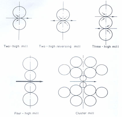
The thickness tolerance on plate cut from hot-rolled strip is roughly half that on material produced via the four-high mill. Close thickness tolerances allow customers to provide ballistic protection and optimized weight levels.

The advantages of ballistic steels can also be favorably combined with those of fiber composite materials.

Advantages of ballistic steels can be summarized in the following way:

  • Defined ballistic properties
  • Very close thickness tolerances
  • Maximum flatness tolerance 6 mm/m for all thicknesses
  • Good cold forming properties
  • Available thicknesses 3 to 150 mm
  • Good weldability.

go to topbeck to top

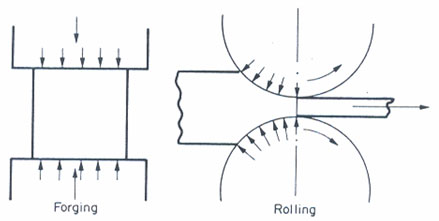
Forging

 
Abstract:
Forging was the first of the indirect compression-type process and it is probably the oldest method of metal forming. It involves the application of a compressive stress, which exceeds the flow stress of the metal. The stress can either be applied quickly or slowly. The process can be carried out hot or cold, choice of temperature being decided by such factors as whether ease and cheapness of deformation, production of certain mechanical properties or surface finish is the overriding factor.
There are two kinds of forging process, impact forging and press forging. In the former, the load is applied by impact, and deformation takes place over a very short time. Press forging, on the other hand, involves the gradual build up of pressure to cause the metal to yield. The time of application is relatively long. Over 90% of forging processes are hot.
 
 
Forging was the first of the indirect compression-type process and it is probably the oldest method of metal forming. It involves the application of a compressive stress, which exceeds the flow stress of the metal. The stress can either be applied quickly or slowly. The process can be carried out hot or cold, choice of temperature being decided by such factors as whether ease and cheapness of deformation, production of certain mechanical properties or surface finish is the overriding factor.

There are two kinds of forging process, impact forging and press forging. In the former, the load is applied by impact, and deformation takes place over a very short time. Press forging, on the other hand, involves the gradual build up of pressure to cause the metal to yield. The time of application is relatively long. Over 90% of forging processes are hot.

Impact forging can be further subdivided into three types:

  • Smith forging,
  • Drop forging,
  • Upset forging.

Smith Forging

This is undoubtedly the oldest type of forging, but it is now relatively uncommon. The impact force for deformation is applied manually by the blacksmith by means of a hammer. The piece of metal is heated in a forge and when at the proper temperature is placed on an anvil. This is a heavy mass of steel with a flat top, a horn which is curved for producing different curvatures, and a square hole in the top to accommodate various anvil fittings. While being hammered the metal is held with suitable tongs.

Formers are sometimes used; these have handles and are held onto the work piece by the smith while the other end is struck with a sledgehammer by a helper. The surfaces of the formers have different shapes and are used to impart these shapes to the forgings. One type of former, called fuller, has a well-rounded chisel-shaped edge and is used to draw out or extend the work piece. A fuller concentrates the blow and causes the metal to lengthen much more rapidly than can be done by using a flat hammer surface. Fullers are also made as anvil fittings so that the metal is drawn out using both a top and bottom fuller. Fittings of various shapes can be placed in the square hole in the anvil.

The working chisels are used for cutting the metal, punches and a block having proper-sized holes are used for punching out holes. Welding can be done by shaping the surfaces to be joined, heating the two pieces then adding a flux to the surfaces to remove scale and impurities. The two pieces are then hammered together producing welding.

The easiest metals to forge are the low and medium carbon steels and most smith forgings are made of these metals. The high carbon and alloy steels are more difficult to forge and require great care.

Drop Forging

This is the modern equivalent of smith forging where the limited force of the blacksmith has been replaced by the mechanical or steam hammer. The process can be carried out by open forging where the hammer is replaced by a tup and the metal is manipulated manually on an anvil.

The quality of the products depends very much on the skill of the forger. Open forging is used extensively for the cogging process where the work piece is reduced in size by repeated blows as the metal gradually passes under the forge.

The cogging of a prismatic bar can be used to assess the parameters involved and how they are controlled. The objective is to reduce the thickness of the work piece in a stepwise sequence from end to end. Several passes may be required to complete the work and edging is usually carried out to control the width. The reduction in thickness is accompanied by elongation and spreading. The relative amounts of elongation and spread cannot be calculated theoretically but they have been determined experimentally for mild steel.

Die drop forging. Closed-die drop forging is widely used and the tup and anvil are replaced by dies. Matching dies fit into the anvil and the tup. The dies have a series of grooves and depressions cut into them and the work piece is passed in sequence through a shaping series.

These stations have names such as fullering, blocking, edging, bending and cut off. Where several stages are involved, care must be taken to ensure that the metal does not become excessively chilled before the last station is reached. To ensure that the die cavity is completely filled the volume of the starting billet is greater than that of the final forging. The excess metal appears as a "flash" at each stage, this is a thin fin around the perimeter of the forging at the parting line. This flash is cut away in a further press operation generally at a high temperature. The weight of flash may be a small percentage of the total weight for forgings of simple shapes but may exceed the weight of the actual forging for those of complex shape.

Each size and shape of forging will thus require a separate set of forging and trimming dies. The production tolerance for the initial metal must involve excess, e.g. ~10 mm. The over-tolerance metal is accommodated by a gutter around the die cavity which allows the formation of the fin referred to earlier.

Upset Forging

This process was developed originally to gather, or upset metal to form heads on bolts. Today the purpose of this machine has been broadened to include a wide variety of forgings.

It is essentially a double-acting press with horizontal motions rather than vertical. The forging machine has two actions. In the first, a movable die travels horizontally towards a similar stationary die. These two dies have semi-circular horizontal grooves, which grip the bars. A bar heated at the end is inserted between the movable and stationary die. While thus held, the end of the bar is upset or pressed into the die cavity by a heading tool mounted on a ram, which moves towards the front of the machine.

If hexagon heads are desired, a heading tool will upset some of the metal into a hexagon-shaped die cavity. For more complex forgings, as many as six different dies and heading tools may be used in turn in a similar manner to the different stations in die drop forging.

Press Forging

Whereas impact forging usually involves a mechanical press, press forging, on the other hand, requires hydraulic power. The largest forgings are invariably produced on large hydraulic presses. These have vertically moving rams, which move down slowly under considerable pressure.

A typical press forge would be capable of loads of the order of 6000 to 10000 tones. Forgings up to 100 tones weight can be handled easily in this forge and the highest-quality products are manufactured by this technique.

Structure and Properties of Forgings

Forgings are invariably produced by the hot-working process and this controls the resultant structure and properties. There are, however, important differences in forgings produced by different techniques.

The fact that the impact forge applies a stress for a very short period compared to the long period for the press forge results in totally different structures in the product. In the case of impact, the mechanical working is concentrated in the surface layers, since rapid removal of the stress after the blow results in metal relaxation before the effect of the blow has penetrated into the center. Impact forging of a large "as cast" piece of metal at high temperature will result in a very inhomogeneous structure, the outside layers showing a typical hot-worked structure whilst the center is still as cast. Any attempt to achieve greater penetration by increasing the impact load usually leads to internal cracking. Impact forging is therefore limited to relatively small work pieces.

Press forging invariably results in total penetration of the effect of the applied stress into the center of the work piece. The process is generally less severe on the metal than impact. The end result is a more homogeneous product having very high quality. Since the process is much slower and the equipment used is much larger, press forged articles are more expensive than impact forged components.

go to topbeck to top

Application of New Hot-Rolled High-Strength Sheet Steels

 
Abstract:
Interest in high-strength steel has a lengthy history in the steel industry. Recent development of high-strength low-alloy (HSLA) sheet steel depends upon the large amount of technical information available in this field. In response to the automobile industry’s demand to reduce overall vehicle weight and thereby improve fuel economy, and to satisfy safety and crash-worthiness requirements, the steel industry has developed a large variety of steels and processes for producing high-strength hot-rolled and cold-rolled steel sheets.
Several types of hot-rolled dual-phase sheet steels have been compared in this article with conventional micro alloyed steels through various forming tests.
 
 
Several types of hot-rolled dual-phase sheet steels prepared by simple temperature control in hot strip mill or by heat treatment on a continuous annealing line have been compared in this article with conventional micro alloyed steels through various forming tests.

Thickness of these steels ranges from 1.8 to 2.5 mm and yield strength from 300 to 520 MPa. Forming tests employed include stretching, drawing, flange stretching or hole expansion, and simulative model forming of automotive parts such as rear axle housing and spring support, and the behavior of these sheets is discussed.

Interest in high-strength steel has a lengthy history in the steel industry. Recent development of high-strength low-alloy (HSLA) sheet steel depends upon the large amount of technical information available in this field. In response to the automobile industry’s demand to reduce overall vehicle weight and thereby improve fuel economy, and to satisfy safety and crash-worthiness requirements, the steel industry has developed a large variety of steels and processes for producing high-strength hot-rolled and cold-rolled steel sheets.

The overall suitability of various steels for automobile body panel applications is assessed by evaluating their characteristics with regard to the performance requirements (formability, weldability, paintability, etc.). The formability of the steel sheets is perhaps the most important requirement for automotive component applications.

The aim of this article is to shed some light on the properties of steels which are controlled by the manufacturing conditions, and to recover the loss of formability that occurs as strength increases. The possible applications to automotive parts can be divided into two general categories, namely body panels and structural and safety-related parts. This article describes the formability of hot-rolled high-strength sheet steels for the latter category and the principal material properties which become the indication when producing such materials.

Dual phase steels, which have much better ductility for a given strength than conventional high-strength steels, have been developed. They have microstructures consisting of two major phases: martensite and ferrite. The suitable method of making these steels is to roll to the required thickness and then make use of heat treatment on a continuous annealing line. Another method is to find out the cooling condition and steel compositions which achieve typical dual phase properties directly from a continuous hot strip mill. These lead to the availability of hot-rolled dual phase steels made by two different methods and substantially different compositions.

Despite the differences between the steels, it is necessary for the automotive industry that they should have similar forming behavior and performance. This study therefore compares some of the properties for nine as- hot-rolled dual phase steels, two continuously heat treated dual phase steels, two conventional high-strength steels, and a commercial low carbon steel with yielding strength of 300 to 520 MPa.

The press forming of these steels is studied to gain an understanding of the influence of increasing strength on formability parameters. The formability investigation is performed through an evaluation of the response of the sheet steel in three deformation modes in the forming limit diagram: stretching, plain strain, and drawing.

Stampings are judged acceptable if there are no obvious tears, cracks, buckles, wrinkles, or necks in the finished stamping. In the forming of hot-rolled steels applied to the frame members of automobiles, which generally require thicker sheet than that of exposed panels, it is important that the steels exhibit good stretch flanging and punch stretching ability.

Tension testing is performed on parallel-sided specimens with a nominal width of 25 mm. Testing is carried out using a constant cross head speed, and elongation to fracture measured with a 50-mm gage length extensometer. Average mechanical properties are obtained from a minimum of five specimens in three test directions.

Hole expansion testing is carried out as follows: a 20-mm hole is punched into the sheet before deformation and is expanded with a conical punch. The expansion of this hole prior to the point of failure is referred to as the ratio of hole expansion.

The stretch forming test is performed with a hemispherical and flat bottom punch in which 400 and 450 mm square blanks are held in the die.

Simulative model forming is carried out with two types of dies. One is a spring support of which a character is stretching, and the other is a rear axle housing of which a character is drawing.

Springback is measured after a simple bending over three dies of different radius of curvature. Thickness of specimen is reduced to 1.7 mm by surface grinding in order to establish a constant strain of bending.

Formability parameters affect the ability of a material to be transformed from its original shape into a defined final shape by a specific forming process. Material, process, and shape interact in forming parts; therefore, they must be considered simultaneously in a formability study.

Mechanical properties such as yield strength, tensile strength, total elongation, work hardening exponent, plastic strain ratio, and strain rate sensitivity exponent, which are determined in the tension test, generally indicate the forming behavior of the material. The importance of these material parameters, which all interact in forming processes, depends upon the shape of the part and the manufacturing processes. Better understanding and accurate determination of these forming parameters help to predict the behavior of these steels in stamping operations.

The work hardening behavior of sheet steels is often characterized by the n-value, defined as the exponent in the Ludwig’s equation. For most dual phase steels, and also for highly formable interstitial free steels, the stress-strain curves do not conform to the Ludwig’s equation. To compare the work hardening behavior of the steels, it is suggested that the most useful parameter is the instantaneous work hardening rate normalized with respect to the flow stress. The distinct expression of the work hardening behavior is obtained by this parameter. However, it is tedious to establish the curves of the normalized work hardening rate in the function of the tensile strain.

Hole expansion ratio is influenced by the plastic strain ratio, by total elongation (which affects the critical hole expansion), and by quantity and shape of inclusions (which cause cracks). Results indicates that the hole expansion ratio decreases with the increase of total quantity of inclusions.

As reported previously, sulfide shape control becomes important in achieving a higher ductility along the sheared edge. Without sulfide shape control in these hot-rolled steels, lower expansion can occur due to the tearing which initiates on the punched edge at elongated sulfide inclusions. However, even in a material with sulfide shape control, there is a rather important degradation of sheared edge ductility as strength increases.

It is noted that a high-strength material which has a hole expansion ratio of more than 1.5 may be considered satisfactory, compared with the low-carbon steels. An investigation is made of the influence of the clearance between punch and die when a hole is punched into the sheet. It is indicated that the clearance has relatively little effect on the hole expansion ratio.

For automotive components the formability of sheet steel is determined principally by biaxial stretchability and deep draw ability. The total elongation and work hardening exponent are measures of the biaxial stretchability of sheet, and these parameters decrease as the yield strength of the sheet steel increases. As a general rule, the average plastic strain ratio, which is a measure of deep draw ability, also decreases as strength increases. For all the steels examined, the values are in a very narrow range and similar to those for low-carbon steel.

There is a good correlation between the forming index and work hardening exponent. This test is performed both parallel and transverse to the rolling direction, so the fracture properties of the sheet in both directions can be evaluated. There is a difference in formability due to the rolling direction.

The shape of automotive sheet components is apt to deviate from the design configurations because of various elastic recovery effects including springback. Defects in shape precision of finished parts are responsible for difficulties in assembly processes. Materials must be as uniform as possible with regard to thickness and properties in order to minimize springback after stamping.

Various types of hot rolled dual phase steels are examined by forming tests. Dual phase steels containing manganese and silicium are characterized by improved formability. Good correlation is obtained between the hole expansion ratio and inclusion shape control.

The work hardening exponent is the principal factor determining the press performance of hot-rolled dual-phase steels. In particular, n-value from 5 to 10 percent strain in tension testing is shown to have a good correlation with formability. This will allow the setting of guidelines for optimizing manufacturing conditions for these steels.

It is expected that the superior properties of dual phase steels will result in significant increases in their use for automotive applications in the immediate future.

go to topbeck to top

Austenitic Sandwich Materials

 
Abstract:
Sandwich systems represent an interdisciplinary concept by combining the areas of material choice, production engineering, design and function integration for the fulfillment of the high demands on modern materials. The sandwich material connects the advantages of miscellaneous materials (e.g. low density, high bend resistance, sound and vibration insulation, energy absorption, high load-capacity at a low weight, need adapted qualities) with each other.
 
 
The future developments in mechanical engineering, vehicle and energy system engineering must concentrate on solutions for processes, machines and materials which carefully treat resources and energy and at the same time keep the technical lead with new and innovative products. Lightweight construction concepts are able to be maintained and operated costs efficiently, reduce production costs, increase the product life for economic reasons reliability of use or optimize the freight of payloads.

Steel has become less favorable in previously dominated areas, e.g. in the automobile industry since lightweight materials such as aluminum and magnesium based alloys as well as synthetic materials and composite materials have gained a broad range of acceptance.

Steels with a higher strength and a higher young modulus than conventional steel cannot quite compensate the advantage of these materials for lightweight construction, despite the advantage of a lower price, a better forming behavior, a higher strength and the possibility of recycling without problems. A trend-setting solution for a higher demand of steel use seems possible by the development of high-strength, austenitic steels with a large manganese content. These steels show comparable mechanical qualities, and at the same time are more economical and in addition permit lightweight construction.

Sandwich systems represent an interdisciplinary concept by combining the areas of material choice, production engineering, design and function integration for the fulfillment of the high demands on modern materials. The sandwich material connects the advantages of miscellaneous materials (e.g. low density, high bend resistance, sound and vibration insulation, energy absorption, high load-capacity at a low weight, need adapted qualities) with each other.

Applications

Nowadays these new materials and designs are appreciated as key technologies for innovative research and development. The further development of the materials, the optimization of material applications and the necessary manufacturing method with reduced costs and time are permanent research objectives.

These new compound systems open new, future-oriented applications. The weight reduction is considerable for this task. A combination of steel/synthetic material/steel has the advantage of a higher strength opposite to corresponding steel and, depending on the choice of the steel grade, a high corrosion resistance. These sandwich materials find their way in more and more industrial applications such as automotive-, building-, transport-, chemical-, aerospace- and airplane industry.

The first essays and theoretical based works from to the "sandwich" topic are from 1935-1945. Applications are found not only in aircraft construction but also in the automobile manufacturing industry, in architecture, in shipbuilding engineering as well as in the sports and leisure industry. Some examples are described in the following.

Sandwich sheet metals increasingly find their way into the automobile industry. They are used for car bodies both for of lightweight reasons and for sound reduction. Sandwich materials are used with a homogeneous or inhomogeneous core of foams and other hard materials.

Examples of components of sandwich constructions are cowl application, gear box covers, hoods, car boot covers, oil pumps and chassis frame components. A well known example for the use of sandwich sheet metals in the automobile industry is the lightweight construction bodywork (Ultra Light Steel Auto Body).

Some of the components, such as spare wheel hollow and cowl application were manufactured of steel sandwich sheets. These components can be executed up to 50% lighter with the same properties concerning geometry and function than with normal deep drawing steel. The material consists of two thin steel sheets which are bonded with a thin polypropylene material layer as core material.

Material manufacturing

In one investigation sandwich materials with high-grade steel sheets were researched. They combine a good corrosion behavior and acid resistance with good damping behavior and noise reduction. For the production of the sandwich materials a 0.5 mm thick polyolefin foil was used.

The first manufacturing method to be tested was a press-joining process. This was performed discontinuously by an 8" and 10" rolling stand. The high-grade steel sheet metals [X2CrNiMo17 12-2 (1.4404) and X6CrNiMoTi17 12-2 (1.4571)] with a thickness of 0.5 mm were first cleaned and degreased. The steel was than coated with a defined layer of adhesive. The used adhesive agent is a conventional product based on epoxy with resin. After activating the adhesive the upper sheet metal was joined with a 0.5 mm thick PP/PE-foil in a rolling process. During the next step the produced upper sandwich was bonded with the lower sheet metal, also by rolling. For durable and reproducible adhesive bonding an activation temperature of the adhesive of 254°C +/-2°C was needed. The necessary dwell time of the coated sheet metals was 30 seconds in a stationary convection oven.

The other way to produce sandwich material is the discontinuous method. This manufacturing method was carried out with a cooling and heating system deduced in a laboratory press system. For the sandwich production a sufficient set of the granular material was mixed with the adhesive agent. This mixture was inserted as a packed bed between the cleaned and degreased sheet metals. At temperatures between 260 to 300°C the sandwich materials were then pressed for about 60s. To reach an even core layer thickness, the sandwich material was pressurized at 445 MPa. After the press process the sandwich material annealed to room temperature with a cooling rate of 10°C/min. For adjusting the core layer thickness and the thickness of the complete sandwich material a metal frame was used as a spacer.

These sandwich materials were examined in different tests for the bond strength of the individual layers and for their forming behavior. Deep drawing behavior is for example examined in the Erichsen Test. The height of the cup is a reference value to compare different sheet materials.

The difficulties in the deep drawing process of sandwich systems dwells from the different behavior of the used materials, e.g. polymer and high-grade steel.

The wrinkling of the metal can be counteracted with blank holders for mono materials. The material is forced into the desired flow direction. With sandwich systems, e.g. metal/PP/PE/metal the metal layer can flow despite a blank holder in the polymers, so that it can come to wrinkling in the metal layer. The higher the resistance of the polymer is brought into line with that of the metal, the bigger the resistance is against wrinkling.

For the deep drawing process of sandwich materials the knowledge about the blank holder pressure and force was necessary. Too little blank holder pressure increases the risk of wrinkling.

Conclusion

If some years ago sandwich systems were used only in individual sections, then they will find the way to more and more industry areas today. By the combination of construction and material they offer the substitution of classic mono materials, because next to lightweight construction they offer quantities like anti-corrosion protection and damping.

The development of new materials and technologies still stands at the beginning. New adapted material systems like natural fiber composites, hybrid structures of metals, polymers and ceramics increasingly gain meaning in future. The development for adapted composites, the processing of a material construction matrix for composite materials as well as the improvement on the adhesion and cohesion qualities by shift transitions graduated are future design objectives. Furthermore at the beginning of the material design process the aspects of the environmental protection and recycling have to consider.

Tool concepts and procedures should also be reconsidered for the component production from sandwich materials or be developed newly or adapted to the materials.

Aspects of the environmental protection and recycling are getting more important in these considerations from the beginning of the development. The use of natural fibers can serve as reinforcements in a matrix material between two metal sheets.

The interest in research and development in the area of these new materials has increased strongly during the last few years. In combination with other fields of research, like the nanotechnology, the biotronics, the mechatronics and the material development, the sandwich materials offer a large and important spectrum for the future.

go to topbeck to top

Carbon and Alloy Steel for Mechanical Fasteners

 
Abstract:
Material is furnished in many application variations. The purchaser should advise the supplier regarding the manufacturing process and finished product application as appropriate. Five application variations are:
  • Cold heading
  • Recessed head
  • Socket head
  • Scrapples nut
  • Tubular rivet
Forming is the primary manufacturing operation in the fastener industry and the term includes heading, upsetting, extruding, and forging. These formed parts are produced at very high speeds by metal flow due to machine-applied pressure.
 
 
Specification according to the Standard F 2282, establishes quality assurance requirements for the physical, mechanical, and metallurgical requirements for carbon and alloy steel wire, rods, and bars in coils intended for the manufacture of mechanical fasteners which includes: bolts, nuts, rivets, screws, washers, and special parts manufactured cold.

The term "quality" is being used to designate characteristics of a material which make it particularly well suited to a specific fabrication and/or application and does not imply "quality" in the usual sense.

Material is furnished in many application variations. The purchaser should advise the supplier regarding the manufacturing process and finished product application as appropriate. Five application variations are:

  • Cold heading
  • Recessed head
  • Socket head
  • Scrapples nut
  • Tubular rivet
Forming is the primary manufacturing operation in the fastener industry and the term includes heading, upsetting, extruding, and forging. These formed parts are produced at very high speeds by metal flow due to machine-applied pressure.

The primary forming operation self-inspects the quality of the raw material and imperfections such as seams, laps, and internal pipe which may not be visible are revealed when the material is upset. The absence of bursts, forging cracks, and open seams is strong evidence that the quality of material selected was that intended for the severe upsets of today’s fastener manufacturing.

Manufacture

Melting Practice: The steel shall be melted in a basic oxygen or electric furnace process.
Casting Practice: Steel shall be ingot cast, or continuous cast with controlled procedures to meet the requirements of this specification.
Deoxidation Practice
and Grain Size:
The material shall be furnished in one of the deoxidation and grain size. When not specified, the practice shall be at the option of the manufacturer.
Silicon killed fine grain shall be produced with aluminum for grain refinement. The material purchaser’s approval shall be obtained for the use of vanadium or columbium for grain refinement.
Silicon killed coarse grain practice.
Silicon killed fine grain practice.
Aluminum killed fine grain practice.
Hardenability: Hardenability for steels with a specified minimum carbon content of 0.20% or greater shall be determined for each heat and the results furnished to the purchaser when requested on the purchase order.
Thermal Treatments: The purchaser shall specify one of the following options for thermal treatment on the purchase order:
  • No thermal treatment.
  • Annealed.
  • Spheroidized.
  • Drawn from annealed rod or bar.
  • Drawn from spheroidize annealed rod or bar.
  • Spheroidized at finished size wire.
  • Annealed-in-process wire.
  • Spheroidized annealed-in-process wire.

Rimmed or capped steels are characterized by a lack of uniformity in their chemical composition, especially for the elements carbon, phosphorus, and sulfur, and for this reason product analysis is not technologically appropriate unless misapplication is clearly indicated.

Coarse Austenitic Grain Size: When a coarse grain size is specified, the steel shall have a grain size number of 1 to 5 inclusive. Conformance to this grain size of 70 % of the grains in the area examined shall constitute the basis of acceptance.

Fine Austenitic Grain Size: When a fine grain size is specified, the steel shall have a grain size number greater than five. Conformance to this grain size of 70 % of the grains in the area examined shall constitute the basis of acceptance. When aluminum is used as the grain refining element, the fine austenitic grain size requirement shall be deemed to be fulfilled if, on heat analysis, the total aluminum content is not less than 0.020 % total aluminum or, alternately, 0.015 % acid soluble aluminum. The aluminum content shall be reported.

Materials and Processing

While standard steel grades for rods and bars have been in existence for many years, and have, with modifications or restrictions of one or more elements, long been used for cold forming, ASTM standard presents a distinct selected series of twenty steel grades for cold forming. These have been jointly developed by steel producers and cold heading and forging users under the aegis of the Industrial Fasteners Institute. These twenty grades are designated steel grades and the ranges and limits for the thirteen carbon steel grades for carbon, manganese, phosphorus, and sulfur and alloy steels with copper, nickel, chromium, molybdenum, tin, and silicon.

A significant area of improvement is in the decarburization control and measurement for cold heading rods and bars.

To prepare a material for cold forming it is often spheroidized, which is an annealing treatment that transforms the microstructure of steel to its softest condition with maximum formability. In the hot rolled or normalized condition, steels containing less than 0.80 % carbon consist of the microconstituents pearlite and ferrite. Pearlite, the harder of the two constituents, causes the steels to resist deformation. The harder pearlite is comprised of alternating thin layers or shells of ferrite and cementite, a very hard substance.

In spheroidize annealing, the cementite layers are caused by time and temperature to collapse into spheroids or globules of cementite. This globular form of cementite tends to facilitate cold deformation in such processes as cold heading, cold rolling, forming, and bending.

Boron is extremely effective as a hardening agent in carbon steels, contributing hardenability which generally exceeds the result of many commercial alloying elements. It does not adversely affect the formability or machinability of plain carbon steels. Actually, the reverse is true since boron permits the use of lower carbon content which contributes to improved formability and machinability.

In its early development, some unsatisfactory results produced product which did not have uniform hardness or toughness along with reduced ability to resist delayed fracture. However, many of these problems were overcome by exhaustive research which demonstrated that for boron to be effective as an alloying agent, it must be in solid solution in a composition range of 0.0005% to 0.003%. During deoxidation, failure to tie up the free nitrogen results in the formation of boron nitrides which will prevent the boron from being available for hardening. Research also revealed boron content in excess of 0.003% has a detrimental effect on impact strength because of the precipitation of excess boron as iron borocarbide in the grain boundaries. Many European steels contain higher boron levels than in North America.

When producing a boron steel, titanium and/or aluminum is added and the resulting product is subjected to thermal processing. These two additions are designed to tie up nitrogen to stop it from reacting with boron. The resulting free boron is available to provide excellent hardenability in steel. Both titanium and aluminum nitrides reduce the machinability of the steel, however, when the nitrogen becomes tied up, the formability of the steel is improved.

Silicon and aluminum act as somewhat similar elements with respect to their behavior when added during the steel making process. They both have a high affinity for oxygen and are, therefore, used to deoxidize or "kill" the steel. Deoxidation or "killing" is a process by which a strong deoxidizing element is added to the steel to react with the remaining oxygen in the bath to prevent any further reaction between carbon and oxygen.

When carbon and oxygen react in the bath a violent boiling action occurs which removes carbon from the steel. When the bath or heat reaches the desired carbon content for the grade being produced, the carbon-oxygen reaction must be stopped quickly to prevent further elimination of carbon. This addition is accomplished by the addition of deoxidizers such as silicon and aluminum which have a greater affinity for oxygen than does carbon. This effectively removes oxygen, eliminating the "carbon boil" and killing the heat. Elements other than silicon and aluminum can be used, but these are the most common.

Silicon and aluminum can be added together or individually. This is determined by the type of steel desired. If silicon only is added, that particular batch of steel is referred to as a silicon killed coarse grain practice grade because silicon acts as a deoxidizer without the formation of fine precipitates allowing the formation of large or coarse austenitic grains.

Austenitic grain size is not usually a factor for consideration in cold forming, but has a significant effect in subsequent fastener heat treatment. Aluminum, on the other hand, not only deoxidizes the steel, but also refines the grain size. Like silicon, aluminum removes oxygen from the bath, effectively killing the heat. Aluminum also reacts with nitrogen in the steel to form aluminum nitride particles which precipitate both at the grain boundaries and within the austenitic grains thus restricting the size of the grains; even when the steel is reheated for carburizing or neutral hardening, hence the term fine grain.

When aluminum only is added, the steel is referred to as aluminum killed, fine grain. A third group of steels are referred to as silicon killed, fine grain. In steels of this type, silicon is added as the deoxidizer followed by the addition of aluminum for grain size control.

In the two types where silicon is added, the silicon content can have several ranges with the most common being 0.15 % to 0.30 %. When aluminum is added to these steels for grain size control, the aluminum content is generally in the 0.015 % to 0.030 % range. The aluminum content in fully aluminum killed steels is generally 0.015 % to 0.055 %, somewhat higher on average since the aluminum must both deoxidize and control grain size at the same time.

In selecting the type of deoxidation practice for a particular carbon grade of steel to be used in fastener manufacturing, a number of factors should be considered, such as, heat treated property requirements, heat treat conditions, fastener size, and steel availability, to name a few. Silicon acts as a ferrite strengthener and, therefore, in the absence of aluminum, has somewhat greater hardenability. For the same carbon grade and heat treat conditions with and without aluminum, complete transformation of the fastener core during heat treatment can take place in a larger section using a coarse grain steel.

The disadvantage of silicon killed steels can be reflected in reduced ductility and tool life during cold heading because of its ferrite strengthening characteristic. Aluminum killed steels are usually more formable and hence provide somewhat improved tool life but reduced heat treatment response during heading, particularly in larger size fasteners. For this reason, the recommended maximum diameter for oil quenched aluminum killed carbon grades is typically 0.190 in.

go to topbeck to top

Steel Rolling

 
Abstract:
Rolling is an indirect compression process. Normally the only force or stress applied is the radial pressure from the rolls. This deforms the metal and pulls it through the roll gap. The process can be compared to compression or forging but differs in two respects in that compression takes place between a pair of platens at various inclinations to each other, and that the process is continuous.
Rolling is the most widely used deformation process and for the reason that there are so many versions the process has its own classification.
 
 
Rolling is an indirect compression process. Normally the only force or stress applied is the radial pressure from the rolls. This deforms the metal and pulls it through the roll gap. The process can be compared to compression or forging but differs in two respects in that compression takes place between a pair of platens at various inclinations to each other, and that the process is continuous, Fig. 1.


steel Specif Aplication
Fig.1.

Rolling is the most widely used deformation process and for the reason that there are so many versions the process has its own classification. This can be according to the arrangement of the rolls in the mill stand or according to the arrangement of the stands in sequence. Rolling mills are classified as in Fig. 2.


steel Specif Aplication
Fig.2.

The two-high mill was the first and simplest but production rates tended to be low because of the time lost in returning the metal to the front of the mill. This obviously led to the reversing two-high mill where the metal could be rolled in both directions. Such a mill is limited in the length that it can handle, and if the rolling speed is increased, the output is almost unchanged because of the increased time spent in reversing the rotation at each pass. This sets an economic maximum of about 10 meters.

The next obvious development was the three-high mill, which has the advantages of both the two high reversing and non-reversing mills. Such a mill must, of course, have elevating tables on both sides of the rolls. The roll gap on a three-high mill cannot be adjusted between passes, therefore grooves or passes must be cut into the roll face to achieve different pass reductions.

All three kinds of mill suffer from the disadvantage that all stages of rolling are carried out on the same rolled surface and the surface quality of the product tends to be low. Roll changes on such mills are relatively frequent and time consuming. This type of mill is therefore used for primary rolling where rapid change of shape is required, even at the expense of surface quality.

Four-high mills are a special case of two-high, and in an attempt to lower the rolling load, the work roll diameter is decreased.

There is, however, a risk of roll bending which is avoided by supporting the small work rolls by larger backing rolls. The backing roll diameter cannot be greater than about 2-3 times that of the work rolls, and as the work roll diameter is decreased more and more (to accommodate processes with exceedingly high rolling loads) the size of the backing rolls must also decrease. A point is reached when the backing rolls themselves begin to bend and must be supported hence the ultimate design - the cluster mill.

The principal criticism of the traditional mill is this tendency for roll bending due to its inherent design - the beam principle. Sendzimir proposed a design which eliminated this limitation based on the castor principle where the work roll is supported over ali its face by an array of backing rolls. This principle can be applied to much mills and an installation for rolling stainless steel 1600 mm wide is fitted with work rolls 85 mm diameter.

Continuous rolling mills can be classified according to the arrangement of stands or passes. These are in line in a continuous mill and line abreast in a looping or cross-country mill. Looping and cross-country mills require the workpiece to be bent or turned between stands and are used therefore for rolling rods, rails or sections. Continuous mills are used for plates, strip or sheets. They all require a large capital outlay and are only justified when a large demand for the product is guaranteed.

It is possible to derive an expression for this friction force. Pressure acts radially on the ends of this element, and if the element is located between the point of entry and the neutral point a frictional force acts toward the neutral point. The radial pressure has a horizontal component which tends to reject the metal and prevent it from entering the rolls, whilst the friction force has a horizontal component dragging the metal inward. Whether the metal passes through the rolls depends upon the values of the two horizontal force components.

Primary rolling is a process where large maximum reductions are required in order that the metal can be deformed quickly and cheaply. Such mills have large diameter rolls with surfaces that are roughened or ragged to increase the coefficient of friction.

The rolling load can be minimized by making the radius as small as possible and the roll surface as smooth as possible. This principle is used in the design of cluster mills which are used extensively for foil rolling and consist of small work rolls supported by larger back-up rolls to prevent bending. Even with such mills the rolling loads can still be excessive and recourse is made to devices which apply front and back tension to the metal being rolled.

Foil rolling and finishing mills are generally very different from primary mills which as already seen tend to use large diameter rolls with roughened surfaces.

It is an essential of metal-deformation processes that the tool is only loaded elastically, while the workpiece is flowing plastically. This elastic deformation is generally so small that it can be ignored, but this is not the case in rolling. There are two reasons. One is that rolling loads and stresses can be very large, especially when the workpiece is thin and work-hardened. The other is that the tool in rolling comprises the whole mill-rolls and housing with overall dimensions measurable in meters. This combination can result in very large strains due to elastic deformation divided between mill stand extension "mill spring", roll flattening and roll bending.

Roll flattening. The workpiece passing between a pair of rolls is compressed by the radial stress in them, but the reaction is transferred to the mill bearings and housing, which are capable of only limited yield because of their large dimensions. If an attempt is made to compress thin hard material further, the reaction becomes so large that the rolls deform elastically and the radius of curvature of the arc of contact is increased. The extent of this flattening depends on the magnitude of the reaction stress and the elastic constants of the rolls.

Roll flattening has another effect in that for a given mill there is a minimum gauge below which it is not possible to roll. Any attempt to do so results in greater deformation of the rolls, without any plastic deformation of the strip. With thin gauges as already seen the friction hill becomes very large producing reaction stresses in the arc of contact which exceed the yield stress of the rolls, therefore it is easier to deform the rolls than the metal. As long as the mill is running the rolls will remain circular, but if the load is not removed when it is stopped, deformation will take place to flatten the surface over the area of contact between the rolls.

Attempts to avoid or limit roll bending have involved ways of decreasing the rolling load. This has resulted in small work rolls and four-high mills. But even with these mills a certain amount of roll bending still occurs and is accommodated by cambering the rolls, i.e. making them barrel shaped. With multistand continuous rolling, interstand tension is adjusted to maintain the rolling load to a constant value and so achieve a flat surface. This is an important aspect of shape control in the rolling of strip.

A recent development has been the introduction of hydraulic jacks onto the roll necks thereby altering the roll camber by actually bending the rolls. Results to date indicate that this method will be very successful in controlling strip shape.

All the methods described so far have involved continuous rolling where front and back tension or interstand tension can be used. With single sheet rolling this technique for controlling rolling load cannot be used and therefore the problem of shape control is tackled in another way.

Mill spring or plastic distortion. The reaction to rolling load is called the roll separating force and if the rolls were not held in the mill housing they would indeed separate and reduction of metal would not be possible. The upper roll pushes the top of the housing upwards whilst the bottom roll pushes the base of the housing downwards. The housing is therefore subjected to a tensile stress, which is obviously below the yield stress of the cast steel normally used, but there is a measurable elastic deformation.

The extent depends upon (a) the rolling load, (b) the cross-sectional area of the housing, and (c) the height of the housing. If the extent of this deformation is small the mill is said to be hard or rigid, whilst if it is large, the mill is said to be soft or springy.

It is a characteristic of the mill and can be determined in the following way. The mill is set to a constant roll gap and a series of different pieces of metal are rolled. These produce different rolling loads which are measured. The rolling loads can be varied either by using different gauges of the same metal or by using different metals. A graph is drawn relating rolling load to gauge, the gauge being found by measuring the thickness of the rolled pieces.

go to topbeck to top

Production of Sheet Bimetal

 
Abstract:
Multilayer material is obtained by joining different metals producing a range of different good properties of the constituent metals in the obtained material, like:
- good structural properties of one constituent metal, and good corrosion resistance, shearing and sliding properties or abrasive hardness of the other constituent metal, and
- good conductivity of one metal, and good heat resistance of the other constituent metal.
It should be noted that price of the article made of multilayer material becomes quite low due to substitution, even up to 90%, of high grade alloys and scarce materials with cheap structural steel.
 
 
Multilayer material is obtained by joining different metals producing a range of different good properties of the constituent metals in the obtained material, like:
 
  • good structural properties of one constituent metal,
  • good anticorrosive property, shearing and sliding properties or abrasive hardness of the other constituent metal,
  • good conductivity of one metal, and
  • good heat resistance of the other constituent metal.

    It should be noted that price of the article made of multilayer material becomes quite low due to substitution, even up to 90%, of high grade alloys and scarce materials with cheap structural steel.

    Low Carbon Steel – Stainless Steel

    Bimetal in this particular combination, absolutely substitutes stainless steel in all types of steel structures, securing absolute corrosion resistance in the aggressive environments and very high toughness of the structure at the same time, the quality that stainless steel it self does not possess.

    Selection of the basic layer of a bimetal depends on the following working conditions of the equipment made of that specific bimetal: temperature, working pressure and impact load. In most cases carbon and low-carbon steel with high yield points and steels resistant to ageing and so called "creeping deformation" are used as the basic layers of this kind of bimetal.

    The secondary layer, i.e., the adherent layer secures high resistance to corrosion in the aggressive ambient and frequently chrome-nickel (Cr-Ni) steels are used as the adherent layers.

    Technological character of bimetal considerably widens the scope of use of stainless steel in different industries. In comparison to stainless steel, bimetal is more successfully used in the construction of: reservoirs, tanks for aggressive liquids and gases, heat exchangers, digesters, mixers, agitators, hydroelectric power stations (turbine blades) dam gates, pipeline components, steam pipeline components, steam separators and many others.

    Carbon Steel – Titanium

    With the development of processing and chemical industry, high alloy Cr-Ni steels proved to be not enough resistant in many cases. Advantage of titanium over other anticorrosive metals is that when titanium corrodes, corrosion does not take place at some individual area or areas of the metal but uniformly over the whole area of the metal. Pitting or intracrystal corrosion is a very rare case.

    Titanium its alloys in combination with structural steel, besides securing high anticorrosive resistance in an aggressive ambient, considerably improve the structure of the equipment working in acid-baths, like, hydrochloric acid, sulphuric acid and sodium chloride.

    Steel Sheet Joined to Copper Sheet or Tombac (CuZn10)

    The bimetal obtained by combining copper or brass with steel has a wide range of application in industry.

    Three-layer bimetal strips are of special interest, they are used for making ammunition. These bimetal strips are also used in the automobile industry for production of cooling radiators, reservoirs and gaskets for motor-heads.

    Bimetal Industrial Cutters

    Bimetal cutters, compared to cutters made of uniform steel only, have many technical, technological and economic advantages. Firstly, in bimetal 90% cheaper structural steel substitutes for expensive tool steel and high speed steel.

    In the case of bimetal only the cutting edge of a tool is made of quality steel. Use of bimetal makes the heat treatment, straightening, grinding and sharpening processes easier and similar.

    In the event of bimetal cutters the possibility of burning of cutting edge during hardening is excluded because the heat is intensively transferred to the structural steel side. Hardness of the cutting edge of a cutter of this kind is high and so is the necessary toughness of the body made of structural steel. That is why they are absolutely safe for exploitation and safe even when they are in direct contact with any worker. These cutters are used in industries, like: paper, metal, wood, textile and similar.

    Bimetal Sliding Bearing (Steel-AlSn20Cu)

    A bimetal bearing comprises of a steel shell with high modules of elasticity, shell which makes a rigid bearing assembly, and a layer of the alloy used which makes the inside wall of the bearing. The hard components are capable of bearing shocks or impacts without causing any deformation while the soft base (plays the role of a shock absorber) absorbs those impacts or shocks and adapts to the journal.

    Sliding bearing alloy has the following characteristics: ability of surface adaptation, ability of adhering to oil layer, small coefficient of expansion, good thermal conductivity, good resistance to corrosion in fatty medium and less sensitive to deformation at edge. These bearings are mounted to diesel motors of locomotives, ships, to compressors, aggregates, cranes, heavy vehicles and similar.

    Bimetal Kitchen Utensils

    Multilayer materials have bright prospects in manufacturing metal kitchen utensils because they have considerably higher thermo-mechanical properties compared to those properties of single-layer materials.

    Manufacturing of bimetal kitchen utensils differs from the manufacturing of present generation metal kitchen utensils only in deep drawing of bimetal straight into utensils without any subsequent welding of heavy thermo-bottoms. By bimetal kitchenware has a very artistic look, its inside is made of 18/10 stainless steel while the outside is made of a high-polished copper or brass layer.

    Heat Exchangers

    Heat exchangers, particularly tubular heat exchangers are very frequent components of equipment used in processing industry. Generally, most of these heat exchangers are in direct contact with aggressive mediums during exploitation, so it is essential that their parts are made of stainless steel or titanium. Due to heavy consumption of high alloy and scarce materials, it is economic that massive heat exchangers are made of bimetal.

    In the case of tubular exchangers, welding of pipes to the pipe wall of exchangers is a bottle-neck in the manufacturing process. Technology of welding by explosion energy secures absolute homogeneity of the joint, because it creates a genuine metallic connection between the pipe and the pipe wall of the exchanger where toughness of the joint is higher than toughness of the weaker metal.

    Welding of metal by explosion energy is widely used for manufacturing different types of panel or plate heat exchangers also. Cooling ducts are cut on a steel plate first, over which a thin plate layer of stainless steel or copper is built-up (welded). Deformation of ducts during exploitation itself is negligible because they cool intensively during exploitation. Repairing of heat exchangers (due to wear of the thin plate of stainless steel or copper during exploitation) heads to welding of a new plate by explosion energy.

    Electro Contacts

    Bimetal Steel-Aluminum serves as the intermediate joint of steel and aluminum in the structures for obtaining aluminum. Today bimetal, obtained using explosion energy, is the only dependable solution for electrolysis of clay, because use of this type of bimetal reduces electrical resistance of the contact even five times and extends the exploitation time more than double compared to these factors of bimetals obtained with other technologies of joining aluminum and steel.

    Trimetal Sheet (Steel-Al-Alma4.5) for Shipbuilding

    Aluminum and its alloys have a very bright future in making different structures which are exposed to sea or salt water ambient. Lately aluminum alloys are more and more used as structural material in shipbuilding where the lower construction or hull of a ship is made of steel but the inside metal sheet of hull is aluminum.

    This type of construction considerably increases the carrying capacity of a ship and its maneuvering capability. It is of particular importance that the navigation system of a ship is located in an antimagnetic field.

    go to topbeck to top

  • The Rotary Forge

     
    Abstract:
    Needs for cost reduction in military and civil production of large tubes led to the development of the new manufacturing processes. Large losses in production of large-caliber cannons and other tubes forced factories to develop and apply manufacturing processes that permit fabrication of parts closer to required net shape.
    The state-of-the-art improvement in technology is made possible through a major change in forging methods for large, hollow, high-strength steel alloys by use of a rotary forge machine developed by the Austrian firm GFM. The machine was capable of both hot and cold forging of hollow or solid cylinders having maximum starting diameters of 22 inches and a minimum hole size of 2.5 inches and will forge cannon tubes up to a maximum length of 33 feet.
     
     
    Needs for cost reduction in military and civil production of large tubes led to the development of the new manufacturing processes. Large losses in production of large-caliber cannons and other tubes forced factories to develop and apply manufacturing processes that permit fabrication of parts closer to required net shape.

    The state-of-the-art improvement in technology is made possible through a major change in forging methods for large, hollow, high-strength steel alloys by use of a rotary forge machine developed by the Austrian firm GFM (Geselschaft für Fertigungstechink und Maschinebau AG).

    The machine was capable of both hot and cold forging of hollow or solid cylinders having maximum starting diameters of 22 inches and a minimum hole size of 2.5 inches and will forge cannon tubes up to a maximum length of 33 feet. It was the largest machine of its kind - 195 feet long and weighing 935 tons.

    The machine was located in the USA. This machine has a self-contained forging box in which the work piece is formed by four forging hammers that are axially symmetric and synchronized in such a way that rotational motion of the work piece is interrupted to permit hammer-to-metal contact while the work piece is immobile in order to avoid shearing or surface tearing of the forging. The forging hammers are mechanically driven, generating a maximum force of 1100 tons per hammer. The reaction forces are absorbed in the forging box and are not transmitted to the foundation as with conventional open-die forge presses. This results in a significant reduction in noise level with the foundation remaining vibration-free.

    The complete forging sequence, including loading and unloading, is accomplished through use of a numerical control system. This provides a greater dimensional precision than is possible with conventional forging presses, as the latter are completely operator-skill dependent. With the use of a mandrel device on the machine, the cannon tube is forged with the proper size hole for subsequent finishing operations. Cannon tubes cannot be hot formed as hollows with open-die press forging methods.

    Machine has two large chuck-jaw heads on each side of the forging box. Initially, the work piece is held by only one chuck-jaw. As forging proceeds, the chuck-jaw on the opposite side of the forging box picks up the partially completed forging and finally supports it entirely as the forging is completed. This permits cannon tube forging to be worked its full length in a single pass with minimum material loss.

    Practice showed that material losses in rotary forge are around 8 times less then in conventional practice. It should be noted that "loss" does not imply discarding all the material, as most of it is remelted and recast to produce additional cannon tubes or other items. Since that rotary forge process begins with a hollow work piece that will be obtained from an electroslag refined (ESR) cast ingot, the material loss is markedly less than that for the conventional process.

    In order to obtain an evolution of how well the rotary forge operation is controlled, the tolerances achieved during hot forging were measured. Wall thickness variation ranged between 0.044 to 0.060 inch. The repeatability was excellent since that machine is numerically controlled. To place these values in proper perspective, it should be realized that tolerances maintained for the conventional forging practice are achieved as a consequence of subsequent machining operations which include finish turning the external surface and then trepanning the hole in the solid forging. Rotary-forged internal diameter variations are small and less than one-half of those resulting from conventional practice.

    Since that these methods were used also for production of cannon weapons, where the principal concern are material characteristics of the high-strength steel alloys employed, the influence of the rotary forge process on the material properties was an important consideration. A comparison was made of the properties obtained after heat treatment from conventional and rotary forged tubes for cannons. The mechanical property variations from tube to tube and also within a tube along its length have been determined. It would appear that there is a tendency for the rotary-forged material to display somewhat more uniform mechanical properties. It is equally apparent that the toughness values are consistently higher, and that, too, is beneficial since a greater toughness is associated with a higher fatigue life limit.

    Experiments also were conducted to evaluate the cold forging operational capabilities of this rotary forging machine. It has been done in a single pass reduction of 17 per cent. In this case, the mandrel over which material was formed contained a mirror image of the desired geometry and the proper helix angle of rifling. The rifling form dimensions and tolerances were equal or better than those achieved by conventional rifling practice. In addition, the bore surface finish was better than that achieved through standard practice. The external finish obtained would be adequate with no further machining required as there are no detrimental surface discontinuities.

    Tests were also conducted to determine feasibility of cold forging thick wall cannon tubes. Full size howitzer tubes were successfully cold forged from materials having initial yield strength of 176 ksi (12 bar). This was accomplished in a single pass with an average reduction of 15 per cent. The transverse yield strength is of most importance because the maximum firing stresses are operable in the transverse (hoop) direction. The cannon tube material specification requirements for yield strength and ductility have been met.

    However, the toughness values achieved were only marginal and somewhat below specifications requirements. Additional work is required in terms of tooling optimization, thermal treatment, and the amount of metal flow required in order to achieve satisfactory mechanical properties throughout the finished cannon tube.

    It is obvious that tremendous economic advantages and benefits can be derived from both hot and cold forging of cannon tubes. From the hot-forging application alone, it has been showed that costs of cannon tube forging was reduced by 50 per cent using this process. In the cold forging applications for thin wall tubes, where the rifling can be put in as part of the forming process, reductions of up to 40 per cent in fabrication times were achieved. There are also significant reductions possible in finishing operations of all large diameter and cannon tubes using the machine in the cold-forging mode, and such reductions reflected at lower costs.

    go to topbeck to top

    Electromagnetic Sorting of Ferrous Metals:

     
    Abstract:
    Practice covers the procedure for sorting ferrous metals using the electromagnetic (eddy-current) method. The procedure relates to instruments using absolute or comparator-type coils for distinguishing variations in mass, shape, conductivity, permeability, and other variables such as hardness and alloy that affect the electrical or magnetic properties, or both, of the material. The selection of samples to determine sorting feasibility and to establish calibration standards is also included.

    The two techniques that are primarily used in electromagnetic sorting employ the absolute (single-) and comparative (two-) coil methods. The decision of whether to use single-coil or two-coil operation is usually determined by empirical data.


    Practice covers the procedure for sorting ferrous metals using the electromagnetic (eddy-current) method. The procedure relates to instruments using absolute or comparator-type coils for distinguishing variations in mass, shape, conductivity, permeability, and other variables such as hardness and alloy that affect the electrical or magnetic properties, or both, of the material. The selection of samples to determine sorting feasibility and to establish calibration standards is also included.

    Sorting Practice

    The two techniques that are primarily used in electromagnetic sorting employ the absolute (single-) and comparative (two-) coil methods. The decision of whether to use single-coil or two-coil operation is usually determined by empirical data.

    In the absolute-coil method, the equipment is calibrated by placing standards of known properties in the test coil. The value of the tested parameter (for instance, hardness, alloy, or heat treatment) is read on the scale of an indicator. In the comparative-coil method, the test piece is compared with a reference piece and the indication tells whether the piece is within or outside of the required limits.

    In absolute coil method, a sample of known classification is inserted in the test coil, and the controls of the instrument are adjusted to obtain an indication. The test is then continued by inserting the pieces to be sorted into the test coil, and observing the instrument indication.

    In comparative coil method, known reference pieces representing the minimum or maximum limits of acceptance, or both, are inserted in the reference coil and test coil. The instrument controls are adjusted for appropriate indications. The test is then continued by inserting the pieces to be sorted in the test coil, leaving a known reference in the reference coil, and observing the instrument indication.

    The range of instrument indication must be so adjusted in the initial step that the anticipated deviations will be recognized within the range of readout according to whether two- or three-way sorts are to be accomplished.

    Both absolute and comparative methods require comparing the pieces to be tested with the reference piece(s). Two or more samples representing the limits of acceptance may be required. In the absolute method the electrical reference is generated by a test piece. In the comparative method any electromagnetic condition that is not common to the test specimen and the standard will produce an imbalance in the system. The comparative method is usually more stable, as it normally suppresses all internal and external disturbances.

    The testing process may consist of manual insertion of one piece after another into the test coil, or an automated feeding and classifying mechanism may be employed. In automated setups, it is sometimes necessary to stop each piece momentarily in the test coil while the reading is being taken, especially if low test frequencies are employed.

    Significance and Use

    Absolute and comparative methods provide a comparative measure for sorting large quantities of ferrous parts of stock with regard to composition; condition; and structure or processing, or both.

    The comparative or two-coil method is used when high-sensitivity testing is required. The advantage of this method is that it almost completely suppresses all internal or external disturbances such as temperature variations or stray magnetic fields. The two-coil method is normally used when harmonic evaluation is employed for sorting.

    The ability to accomplish satisfactorily these types of separations is dependent upon the relation of the magnetic characteristics of the ferromagnetic parts to their physical condition. These methods may be used for high-speed sorting in a fully automated setup where the speed of testing may approach ten pieces per second depending on their size and shape.

    The success of sorting ferromagnetic material depends mainly on the proper selection of magnetic field strength and frequency of signal in the test coil, fill factor, and variables present in the sample. The degree of accuracy of a sort will be affected greatly by the coupling between the test coil field and the tested part and the accuracy with which the tested part is held in the test coil field during the measuring period.

    When high currents are used in the test coil, a means should be provided to maintain a constant temperature of the test standard in order to minimize drift of the test results.